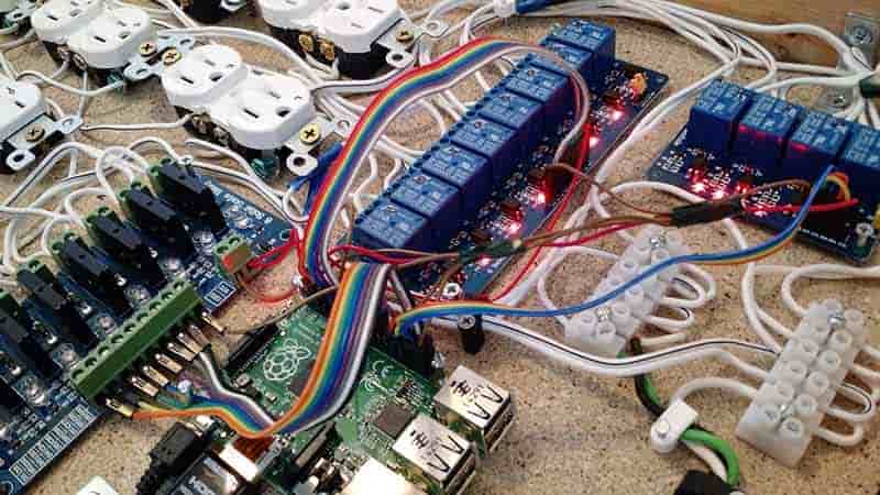
Every electronic device and electrical circuit contains a component called a resistor. This component serves a very important purpose because it stops or reduces the amount of electric current flow that goes to other electronic components. There are many types of possible resistors that exist in an electric circuit. Some of these resistors include metal film resistors, wire wound resistors, thick film resistors, thin-film resistors, surface resistors, network resistors, and more.
No matter what type of resistor you have in your electric circuit, it is either going to be a pull-up resistor or pull-down resistor. Are you curious to know the difference between the two? Let’s example them below.
Pull-Up Resistor
Fixed value resistors are the best way to describe pull-up resistors. These are resistors that stay connected in between a particular pin and the voltage supply. You will typically see around 5 volts or more available for the voltage supply. Whenever a driving signal does not exist, the pull-up resistors define the voltage, whether it is voltage coming in or going out.
Pull-up resistors are typically found in digital logic circuits and microcontrollers. They’re used in conjunction with switches, transistors, and other types of electronic components. The value of the average pull-up resistor will vary, according to the application in question. But a value of 4.7kΩ is not uncommon for a pull-up resistor.
The purpose of pull-up resistors is to make sure the pin has a well-defined level of logic within the digital logic circuits. If there is no input signal going to the device, then the pull-up resistor will pull the wire to a higher level of logic to make up for it.
If a microcontroller or digital logical circuit did not have pull-up resistors, then the input signal would only be brought down after the switch is closed. But when the switch is open, it would remain afloat until you close the switch again.
Pull-Down Resistor
Pull-down resistors have a similar function as the pull-up resistors. However, the main difference is the pull-down resistors pull the pin to decrease the value rather than to raise the value. The connection of the pull-down resistors exists in between the ground terminal and the appropriate pin. There is also a pushdown switch that is found in the middle of the microcontroller pin and the supply voltage.
When you have a closed switch in a pull-down resistor, there is a higher logical value for the input of the microcontroller. When you have an open switch, the input voltage is pulled down to the ground. Once it reaches the ground, it means there is zero logical value. This prevents the input from being undefined. There must be a greater resistance from the pull-down resistor in comparison to the logical circuit impedance. Otherwise, the voltage will get overpulled, causing the pin input voltage to stay at a constant low logical value no matter what the position of the switch is at.
Read also:
- What is Low Pass Filter and its Applications?
- The Difference between RMS vs PMPO in Power Rating
- Top 5 Best Monitor for Xbox One x and PS4 Pro
- Top 5 Best Personal GPS Trackers for Child
Applications
The average microcontroller has programmable resistors, both pull-down and pull-up resistors. That way, the microcontrollers don’t need to have as many external components. In most cases, pull-down resistors are not utilized as much as pull-up resistors.
Digital converters and analog converters typically use them to manage the flow of electric current that goes into the resistive sensor. The I2C protocol bus is another application that uses pull-up resistors. In this application, they cause one pin to serve as either an output or an input. If the bus is not connected to it, the pin floats in a state of high impedance. The pull-down resistors offer a known output impedance by serving as outputs in the application.


