When an electronic circuit is manufactured, it is made to be either a series circuit or a parallel circuit. The difference between these circuits relates to how the resistors are connected to each other. If you have a combination of resistor connections where each resistor is linked together “one after another,” then it is a series circuit. But if the resistors are connected “over one another,” then it is a parallel circuit.
Although there are several types of resistors, their linkage within the circuit has a big impact on how they function. Basically, the power ratings of the resistors are what make them different. Electrical engineers need to know these power ratings because it tells them the amount of power in which the resistors can tolerate before they’re damaged. Not only that, but they can determine the accuracy of the values given to them.
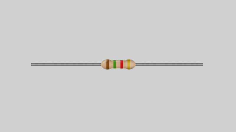
When you have two resistors linked together one after another in a series circuit, then it has a high level of resistance. But if the resistors are connected over one another in a parallel circuit, then it has a lower level of resistance. The values of the resistors are represented by specific color bands that you can see on the outside of them.
The colors of the bands include white, gray, purple, blue, green, yellow, orange, red, brown, and black. A specific number is assigned to each color. Any experienced electrician or electrical engineer is going to understand what number is associated with each color.
Series vs. Parallel
There are a variety of configurations in which the resistors of the electronic circuits can be used. The total circuit resistance is calculated by identifying the parallel resistors and series resistors of the circuit. The total resistance can also be referred to as equivalent resistance.
The “one after another” resistor connections within a circuit means you have series resistors. To calculate the equivalent resistance of your series resistors, you simply figure out the value of each resistor and add all the values together. For example, if you have five series resistors that are represented as R1, R2, R3, R4, and R5, then added all their values together will give you the total resistance found throughout the voltage.
The “one over another” resistor connections within a circuit means you have parallel resistors. This means the resistors don’t directly run into each other, but rather they are across from one another. To give you a better picture of what this looks like, think of two parallel roads next to each other outside. Even though they are not directly connected to each other, they are across from each other within close proximity.
To calculate the total resistance of parallel resistors, you don’t add up all the values of the resistors as you did with the series resistors. After all, the series resistors had an even flow of electricity passing through them. Parallel resistors are different because they have different levels of current in each resistor, which means the values of the resistors are not even. Since each resistor gives the current an extra path to flow through, the formula of total resistance requires you to divide the number one by each of the resistor values and then add them all together.
Read also:
- Wheatstone Bridge (Application and Measurement)
- The Difference between Linear VS Rotary Potentiometer (Pros and Cons)
- Top 5 Best Headband Magnifier with Light
- Top 5 Best Espresso Machine Under $200
For example, let’s say the resistor values of R1 + R2 + R3 are 4 + 5 + 20. If this has parallel resistance, then you would change those values to 1/4 +1/5 + 1/20. When you add up those values, the remaining fraction is ½. However, 1/R is equal to this answer. Therefore, you must cross multiply the numerators with the dominators to come up with the final answer of 2 Ohms.


