 by
by Before you can understand the function and principle of potentiometers, you must understand the function and principle of resistors. A resistor is an electrical device that is found in most electric circuits. Its function is to limit the flow of the electrical current within the circuit. In other words, the flow of the electrical current is restricted by the resistance of the resistor device.
Think about the way a light bulb works. When electricity is sent to the light bulb, the electrons within the electricity will flow through the resistor. From there, the resistor will either convert the electrons into light, heat or both. Each time you flick the light switch on the wall to turn the light on in your room, the resistor inside the light bulb has converted electrons into light.
Getting back to the definition of a potentiometer, it is basically a type of resistor that allows you to adjust the resistance by moving a slider or turning a knob. If you have a special type of light switch that allows you to adjust the brightness of your light sources, then it must have potentiometers in them. In fact, a television or radio that lets you adjust the brightness, contrast or volume will have potentiometers in them too.
What does this all mean? Potentiometers give you the ability to control how much electricity flows into a particular electronic component. In 1872, Thomas Edison invented the very first potentiometer. In those days, the invention was known as a coiled resistance wire rheostat. This was the first prototype of the carbon resistor that we all use today in our radios and televisions. If it weren’t for these carbon resistors, there would be no way to adjust the volume, contrast, color, and brightness of these devices.
Although carbon potentiometers are still used today, some electronics manufacturers may use wire potentiometers and plastic potentiometers instead. Wire potentiometers tend to be more powerful than carbon potentiometers. So, if you have sophisticated electronics that require more advanced adjustments, then wire potentiometers may be more appropriate for that. Plastic potentiometers are no different than carbon potentiometers in terms of power, but they do last longer because they’re better quality.
Three Terminals
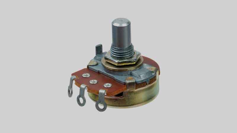
A potentiometer has three terminals. Two of the terminals are fixed terminals. You have one fixed terminal on one side and another fixed terminal on the other side. Electricity flows from one terminal to another. This is the input voltage that comes into the circuit from an outside power source. The voltage consumes the entire potentiometer.
In between the two fixed terminals is a third terminal with a wiper or slider. It is sometimes called the wiper terminal or slider terminal, depending on which one is connected to it. The slider moves in a clockwise or counterclockwise direction. Since the slider is a voltage divider for resistance purposes, the voltage that passes through the sliding contact will convert into an output voltage that is less powerful. The reduced voltage remains between the sliding contact and the fixed terminals.
Do not confuse rheostats with potentiometers because they are two different things. Even though they’re both resistors, a rheostat only has a sliding terminal and one fixed terminal. Rheostats are more suitable for devices that control power, such as elector motors for speed and electric oven for temperature. Potentiometers are found in electric devices that require the same amount of power, such as computers and radios.
Read also:
- Top 5 Best Transistors for Audio Power Amplifier Circuits
- 7 Types of Vacuum Cleaner in Housekeeping
- Top 5 Best Wearable Bluetooth Neck Speakers
- Top 5 Best Automatic Watches Under 500
Conclusion
Rotary potentiometers and linear potentiometers were the two most common types of potentiometers. Now there are digital potentiometers which offer better precision and functionality for digital electronics that allow you to adjust the screen brightness, tune filters, adjust sound volume, and so on.
